- Products
- Finishing robots
UNI-CLEVER - Oscillating machines
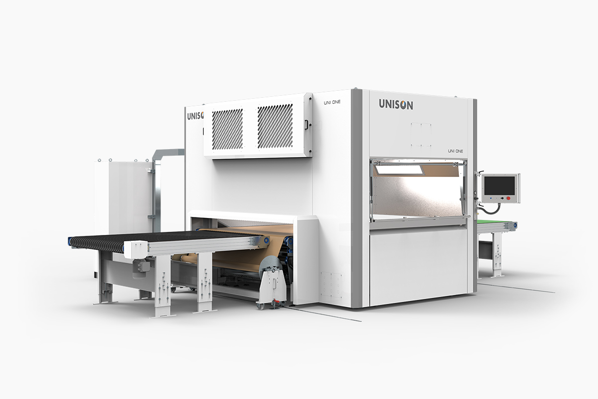
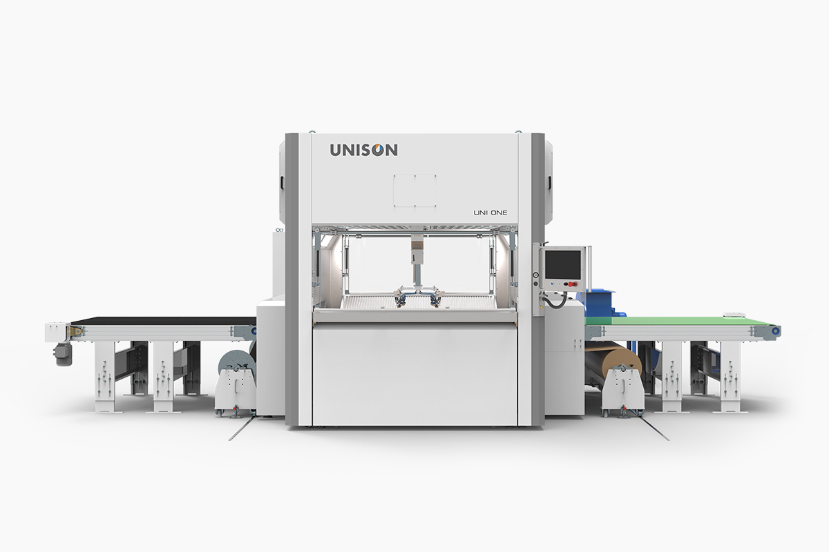
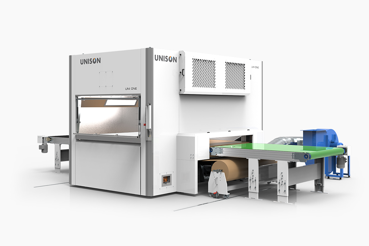
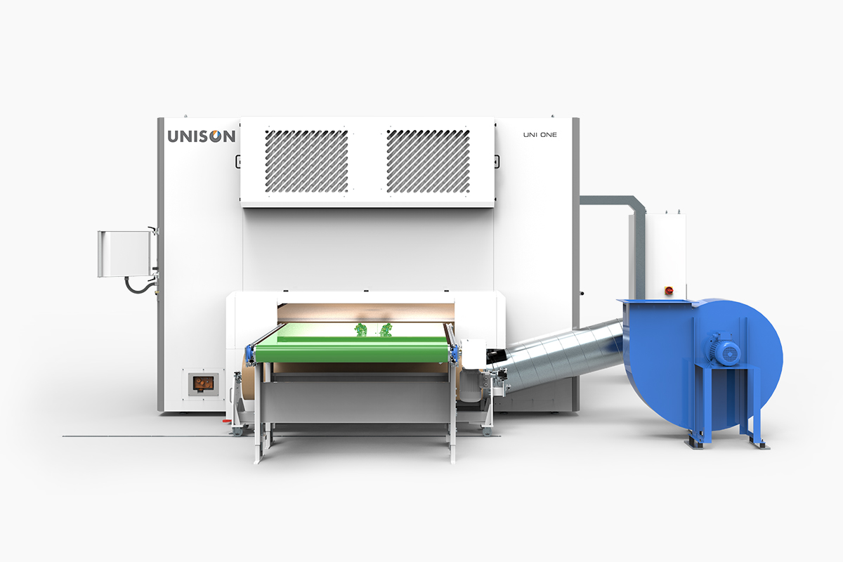
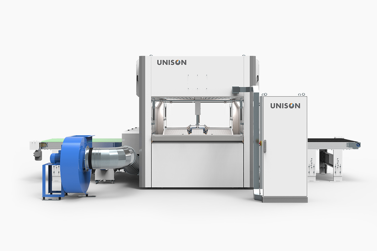
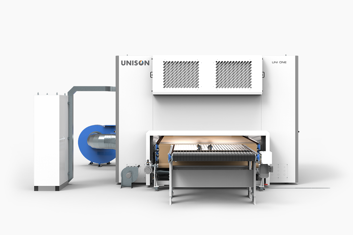
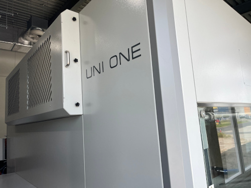
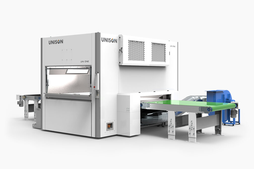
UNI-ONE - Painting machines
UNI-SLIM - Dryers
- UNISON Finishing lines
- Grinding robots
UNI-GRIND - Surfaces cleaning stations
powierzchni UNI-CLEAN - Additional devices
- Painting equipment
Finishing robots
UNI-CLEVEROscillating machines
UNI-ONEPainting machines
UNI-SLIMDryersUNISON Finishing linesGrinding robots
UNI-GRINDSurfaces cleaning stations
powierzchni UNI-CLEANAdditional devicesPainting equipment
- Industries
- Company
- Lab
- Training


