


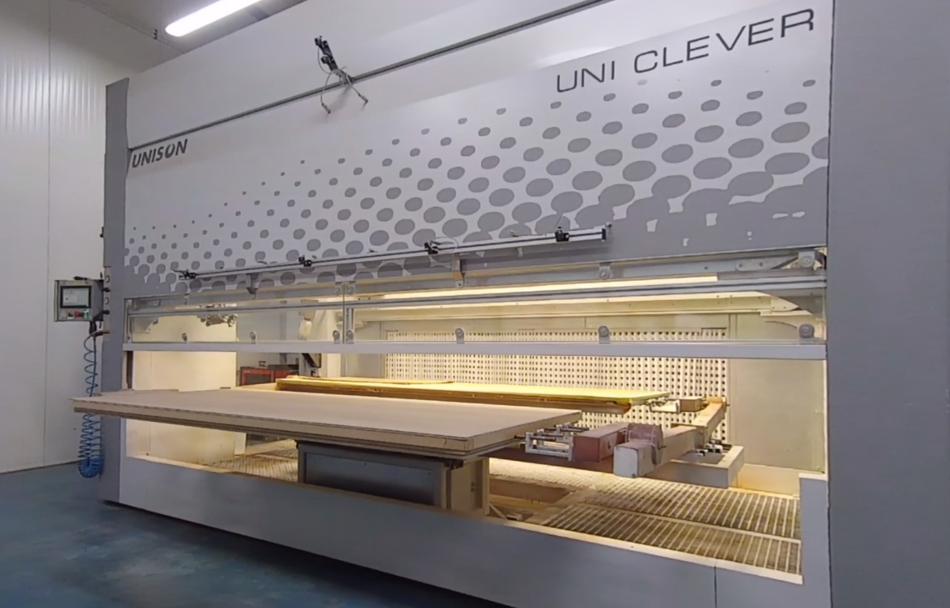
- The painting robot is equipped with a turntable table, which is responsible for transferring the elements to the painting zone
- The turntable increases the efficiency of the painting process and shortens loading and unloading time
- A hydraulic scissor lift installed in the painting booth allows the full height of elements to be painted during one loading
- The operation of paint guns placed in a closed cabin of a finishing robot is possible in five axes (X, Y, Z, A, B)
- It is possible to set various operating modes to optimize the efficiency of the entire painting process
- It is possible to place the device in existing painting booths, using a previously installed air supply and exhaust system
- The painting robot is intended for the application of virtually all types of painting materials available on the market, including such as:
- Stains: water-based, nitro-based, spirit-based, solvent-based
- Varnishes: polyurethane, acrylic, nitro, water-based and water-based UV
- Paints and enamels
- Liquid adhesives used for gluing “finish” foils
- It is possible to apply paint materials using low and/or high-pressure technology in order to select the best application parameters for a given paint material
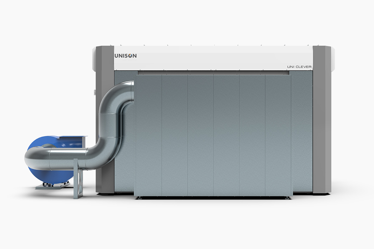
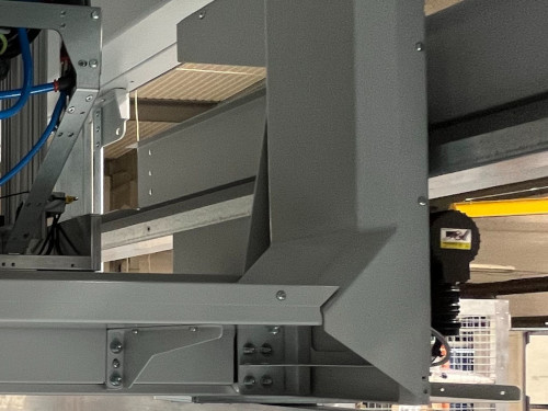
- The case of the device is made of a steel frame with a welded structure to ensure the highest stiffness and durability of the device during dynamic operation of the painting head for many years of operation
- The frame structure of the device is covered with paint with increased resistance to paint materials and cleaning agents recommended for use in UNISON devices
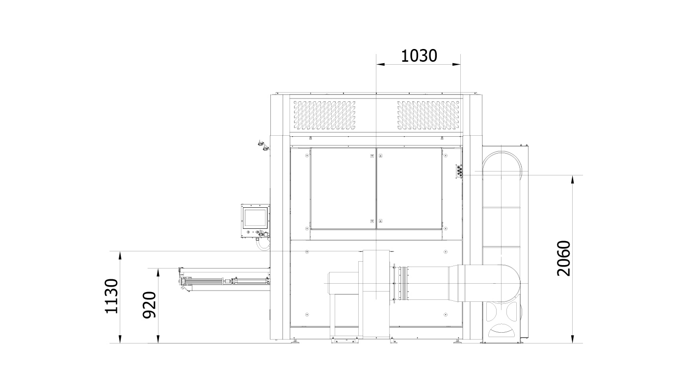
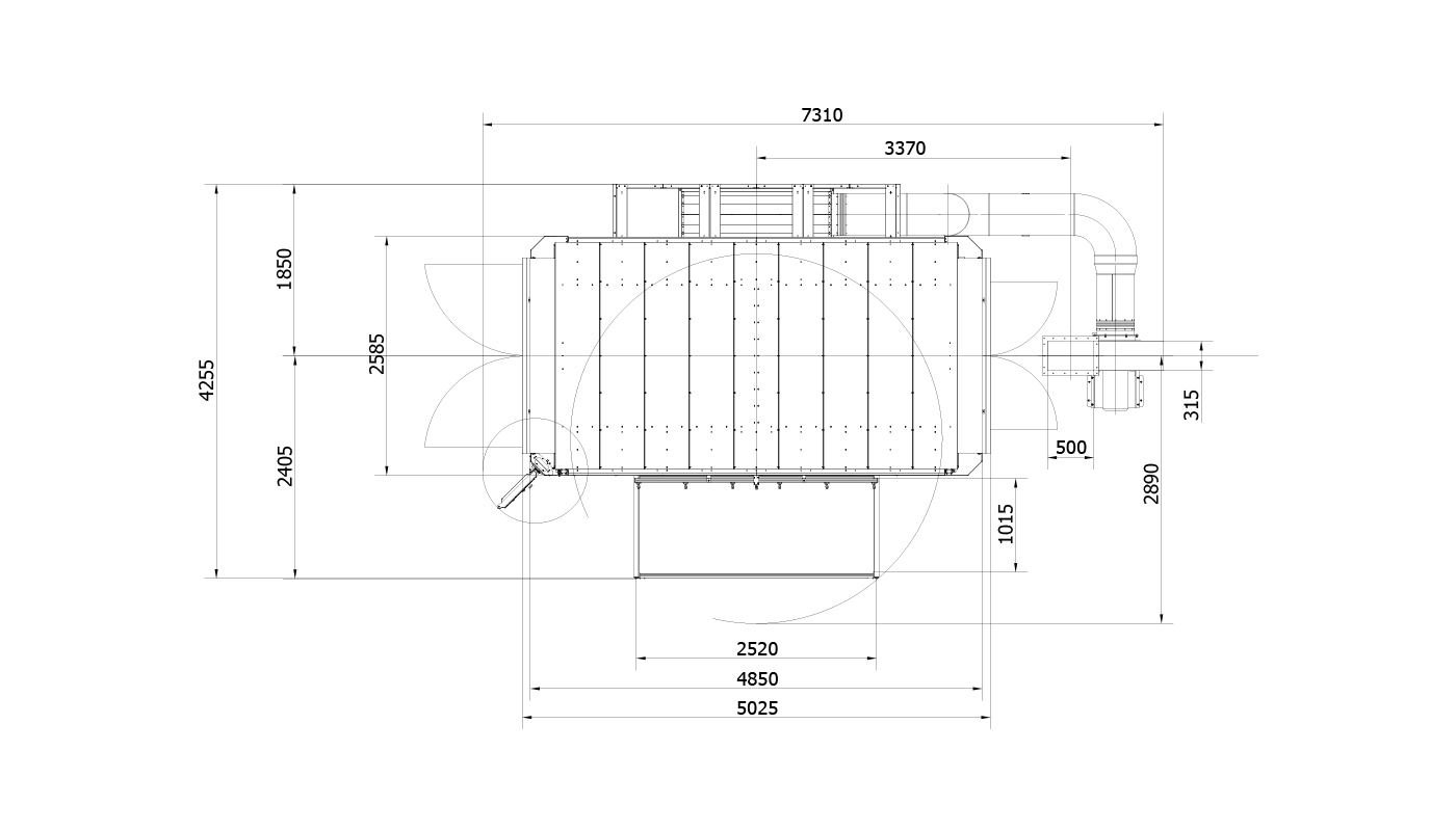
- The compact design of the painting robot along with accessories and equipment minimizes the amount of space necessary for its installation and ongoing operation
- Placing the painting head in a closed painting cabin increases the operator’s comfort, limits the spread of odors accompanying the painting process and allows you to control the air flow in the painting zone
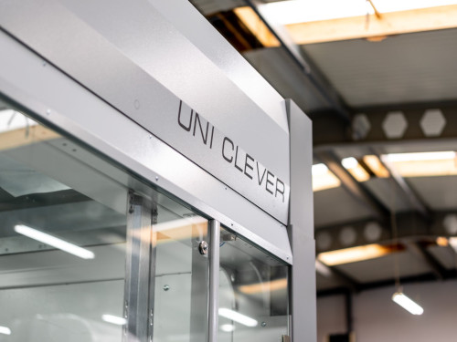
- The large glazing area of the painting booth allows ongoing monitoring of the painting process
- The automatic gate (loading/unloading) increases the cleanliness inside the painting booth and reduces the amount of contamination in the painting zone and around the device
- The service door facilitates the operator’s access to the interior of the painting robot and is integrated with an emergency shutdown system if the door is opened during operation
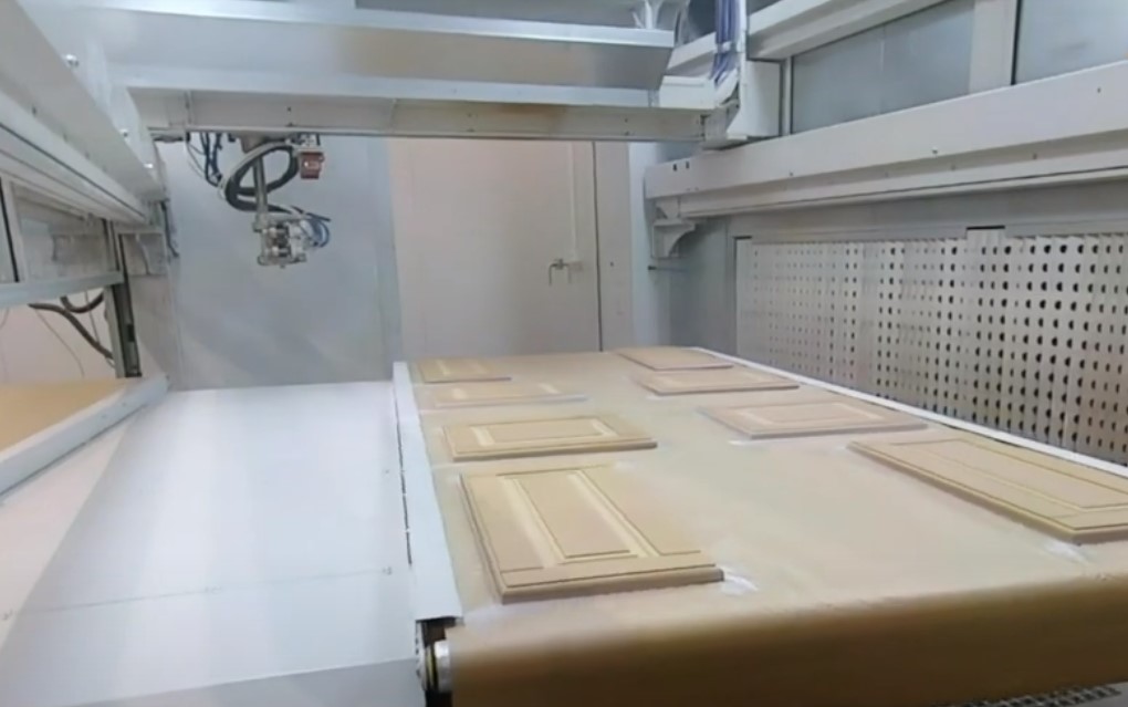
- Inside the closed painting booth there is a detail painting zone with a painting head located above the main conveyor
- Lighting is installed in the internal ceiling of the cabin, which allows the operator to observe the operation of the painting head and monitor the painting process
- In the painting zone there is also a main conveyor on which details to be painted and extraction filters are placed
- Installing a table with a turntable is responsible for transferring elements between the loading zone and the painting zone
- Thanks to the installation of a turntable, the device has a separate loading/unloading zone located outside the device and a painting zone located inside the device
- Equipping a painting robot with a table with a turntable allows to unload painted elements and load new elements while painting elements located in the painting zone
- A table with a turntable increases the efficiency of the painting process and shortens the time of loading and unloading elements
- The use of a turntable allows the entire device to be operated, usually by one operator (if the weight and dimensions of the details allow it), which significantly reduces the costs of operating the device

- The main conveyor is located inside the painting booth
- The tension of the paper increases the effectiveness of its adhesion to the main conveyor and limits the leakage of paint materials onto the lower surface of the painted elements
- The operation of the paper tensioning system is synchronized with the used paper roll drive and the clean paper roll, which automates and optimizes the rewinding process
- Paper rewinding is started by the device operator in order to remove details from the main conveyor and minimize paper consumption
| Type of conveyor | belt |
| Rodzaj pokrycia transportera | smooth perforated belt covered with paper |
| Lenght | 2.580 [mm] |
| Width | 160 [mm] |
| Paper width | 1.100 [mm] |
| Conveyor driver | air motor |
| Moc silnika | 0,25 – 1,1 [kW] (depending on width, length and load) |
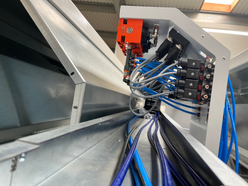
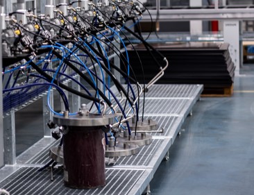
- It is possible to install up to 6 paint circuits without circulation of paint material or up to 3 paint circuits with circulation to enable various configurations of paint systems
- The diameter of the painting pipes is optimally selected to suit the painting processes and the painting materials used
- It is possible to use the so-called systems quick color change and small low-pressure tanks installed at a short distance from the guns to save time when changing the color or type of varnish and to minimize losses of varnish materials during their change
- It is possible to integrate mixing and dosing systems for individual paint components (2K and 3K systems) to select their operating mode from the operator panel of the painting robot
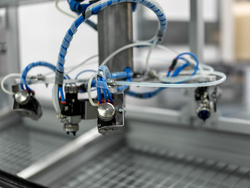
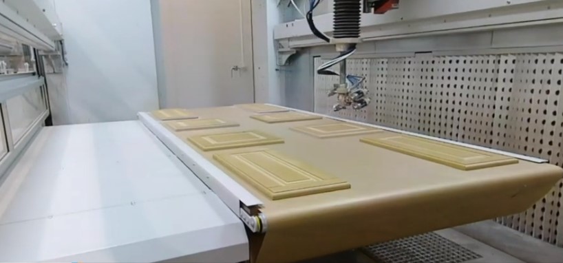
- The painting head located in the painting zone allows for various painting processes
- The painting head is designed to mount various types of automatic painting guns (pneumatic, hydrodynamic, hydrodynamic with air cover, etc.)
- It is possible to install up to 5 painting guns on the painting head in order to carry out as many painting processes as possible without the need to dismantle the guns
- Automatic paint guns are designed for applying paint materials with set operating parameters, minimizing their consumption, reducing the time of the painting process and the consumption of extraction filters
- It is possible to mount paint guns in various ways (e.g. movable/rotary or fixed guns) to best suit the painting processes
- It is possible to apply the paint material in different directions in relation to the painted surface, e.g. painting “in advance”, “back” or perpendicular to the surface
- Paint guns with the paint head can perform programmable movements, moving linearly along the X, Y, Z axes and rotating around their own vertical (A) and horizontal (B) axes
- Pressure regulators installed close to the spray guns enable precise setting of the working pressure and minimize pressure drops in the pneumatic lines
- The service position of the painting head enables ongoing maintenance of the painting equipment by the operator
| Number of painting heads | 1 [pc.] |
| Paint lines from the connections on the paint head to the guns | YES* |
| Pneumatic cables for controlling paint guns | YES* |
| * if the painting equipment is delivered by UNISON. Otherwise – within the scope of implementation by the Ordering Party. | |
- When operating paint guns, up to 5 drive axes of the device are used
- Movements of guns and spray head
- X axis – movement of the painting head along the main working axis of the device, i.e. along the direction of movement of the elements
- Y axis – movement of the painting head transversely to the direction of movement of the elements
- Z axis – movement of the painting head in the vertical direction
- A axis – rotation of the spray guns on the spray head around the Z axis
- B axis – tilt of the spray guns in the vertical plane
- The individual axes are driven by servo drives with smooth speed control
- It is possible to adjust the speed of the painting head every 1 [m/min] and the operating angles of the guns every 1 degree (depending on the given axis)
- The speed of the head and the operating angles of the guns are determined from the device’s operator panel
| The speed of the painting head along the X axis | to 90 [m/min] |
| The speed of the painting head along the Y axis | to 90 [m/min] |
| The speed of the painting head along the Z axis | to 30 [m/min] |
| The angle of rotation of the spray guns relative to the A axis | 360 [degrees] |
| The angle of rotation of the spray guns relative to the B axis | 120 [degrees] |
| Number of simultaneously driven axes during painting | 1 to 5 |
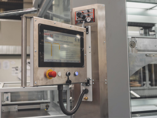
- The main operating parameters of the device are controlled via the operator screen
- The size of the operator screen with a diagonal of approx. 15″ allows you to view all necessary information and parameters related to the operation of the painting robot
- The functionality of the operator screen ensures quick, simple and intuitive operation of the painting robot
- The operator panel is located near the painting zone, on the loading side of the device
- It is possible to place the operator panel on a side of the device convenient for the operator (on the left or right when looking from the loading zone), in order to optimize communication around the device and accelerate operator activities
- The PLC controller is responsible for the current operation of the device and its individual modules
- The PLC controller functions as an industrial computer, controls individual elements and subassemblies of the device and synchronizes their work
- Intuitive software created by the UNISON team enables easy and quick operation of the device and ensures repeatability of painting processes
- It is possible to save and select various painting programs that are responsible for the process of painting the side surfaces of details or horizontal surfaces of elements to be painted in order to simplify operator work and limit the possibility of interference in the previously established painting process
- The device is usually operated by 1-2 trained people who are able to effectively operate the device and conduct the painting process, significantly reducing employment costs
- The final number of staff depends on the intensity of operation of the device, the operating mode of the device and the operator skills of the employees operating the device
Service and inspection doors facilitate daily operation of the device by the operator and maintain cleanliness inside the cabin, and enable quick replacement of supply filters - After connecting the device to the Internet connection, there is a possibility of quick service and diagnostic support by the UNISON team (connection to the Internet connection on the Ordering Party’s side)
- Optionally, the device can be equipped with an intermediate element (tray) adapted to attach e.g. coffin legs or crosses
- Service and inspection doors facilitate daily operation of the device by the operator and maintain cleanliness inside the cabin, and enable quick replacement of supply filters
| Installation side of the operator panel (determined when looking at the device from the loading side | Left/Right |
| Finishing programmes | Surface painting along the X axis Surface painting along the Y axis Cross varnishing of surfaces (X+Y) Surface painting in the so-called attack Edge varnishing Edge varnishing in the so-called attack Painting “hidden” handles |
| Numbers of operators preffered | 1-2 people, e.g. device operator + assistant (depending on the expected performance of the device and work organization) |
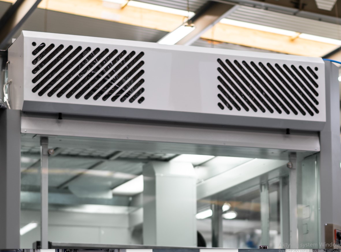
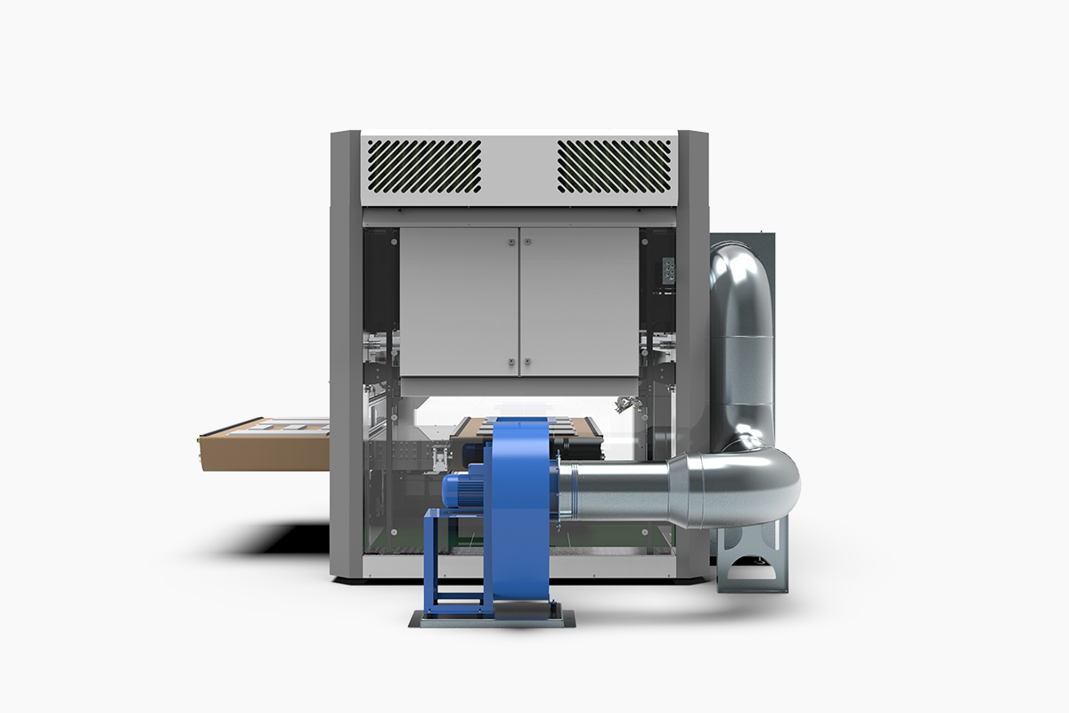
- The painting device allows to manage the supply air flow in order to carry out the painting process in controlled and repeatable quality
- The air intake located in the upper part of the finishing robot supplies the device with fresh air, usually taken from the painting production area, which significantly reduces the costs of its preparation
- A blower fan with adjustable performance is located in the “clean zone” between the air intake and first-stage filters and the second-stage supply filters, in the upper part of the finishing robot
- The location of the fan in the “clean zone” extends its durability and reduces the frequency of servicing
- The efficiency of the blower fan is controlled by coupling the fan motor with the inverter
- The efficiency of the blower fan is regulated by the robot’s operator panel
- It is possible to easily set overpressure, underpressure or balanced pressure (in relation to the pressure prevailing at the place of installation of the device) depending on the needs of the painting process
| Supply fan power | 2 x 0,75 [kW] |
| Supply fan efficiency | 11.800 [m3/h] |
| Performance regulation | motor with inverter |
- The painting robot is equipped with a two-stage supply air filtration system to effectively clean the fresh air from solid impurities
- The supply air filtration system is installed above the painting zone, in the upper part of the painting device
- The first stage of filtration is performed by a cassette filter placed between the air intake and the blower fan
- The second stage of filtration is carried out through non-woven filters placed in the ceiling part, inside the finishing booth
- The structure of the filtration system allows for easy and quick replacement of supply filters
- The class of supply filters is adapted to the painting process implemented in the company
| First stage of filtration (filter at the air intake) | Non-woven filter with cassette structure |
| Second stage of filtration (ceiling filter) | Filter made of synthetic non-woven fabric |
- The air exhaust system is responsible for collecting contaminated air from the painting zone
- Air extraction is performed by an exhaust fan
- A variable capacity exhaust fan allows to set the optimal airflow for a given painting process
- Fan performance regulation is achieved by controlling the operation of the motor with an inverter
- The efficiency of the exhaust fan is regulated from the device’s operator panel
- The exhaust fan is installed next to the painting machine
- By adjusting the fans (supply and exhaust), it is possible to set overpressure, underpressure or balanced pressure (to the pressure in the painting area) depending on the needs of the painting process
| Exhaust fan power | 1 x 3,0 [kW] |
| Exhaust fan performance | 10.000 [m3/h] |
| Dimension of the exhaust pipe of the exhaust fan | 500 x 315 [mm] |
| Fan performance regulation | Motor with inverter |
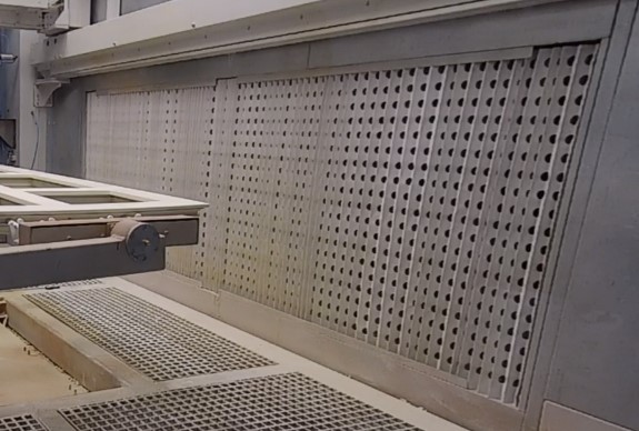
- The exhaust air filtration system is based on a dry filtration system
- Filters are placed on both sides of the main conveyor, inside the painting booth, to effectively clean the air of paint dust and discharge paint fumes to the air ejector
- The painting robot is equipped with a two-stage exhaust air filtration system
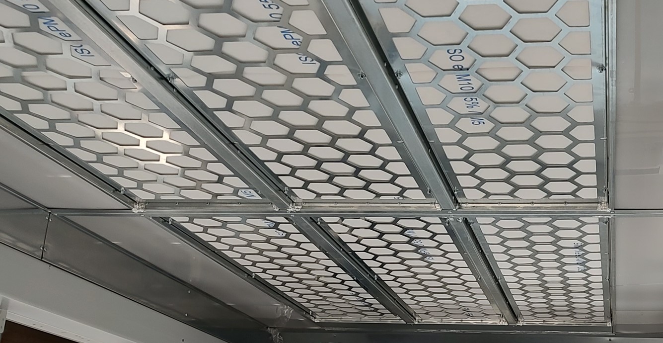
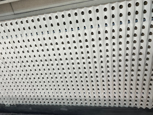
- The first stage of filtration is carried out by a cardboard, pleated, perforated filter (Andrea type), placed directly next to the painting zone
- The second stage of filtration is performed by a “paint stop” non-woven filter placed under the Andrea filter
- Forced air circulation, achieved by the mutual operation of the air blowing and extraction systems, has a positive effect on the quality of the painting process
| Exhaust filters dimension | 2.850 x 1.000 [mm] |
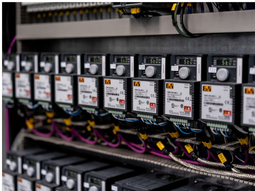
- The device’s electrical switchboard and control cabinet are integrated and incorporated into the device to save space around the device.
- Minimizing the number of electrical and connecting cables between the painting robot and the switchgear and control cabinet increases the safety of the operation of the device
- The electrical switchboard equipment and automation elements responsible for the operation of the device come from renowned international manufacturers


